
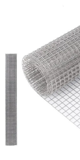
Author: Hebei Zhongman Wire Mesh Products Co., Ltd.
Standards discussed: ASTM A1064/A1064M for applicable steel wire and welded wire reinforcement; the project-adopted concrete design code and edition, such as ACI318 where applicable
1. Definition and application
Welded wire reinforcement is an assembly of intersecting steel wires joined by resistance welding and supplied as sheets or rolls. Plain and deformed wire products are used in concrete applications when they meet the specified material requirements and the structural design. ASTM A1064/A1064M addresses the relevant wire and welded-wire products; it is not a stand-alone design approval for a slab or wall.
The designer must identify the required steel area in each direction, the wire type and grade, placement level, cover, anchorage and lap arrangement. Replacing a scheduled reinforcement system requires review of these matters, not simply matching sheet weight or selecting a wire with a higher tensile-strength value.
        longitudinal reinforcement wires
                 |             |
       ----------+-------------+---------- transverse wire
                 | weld nodes  |
       ----------+-------------+---------- transverse wire
                 |             |
        support chairs maintain designed concrete cover
2. Engineering mechanisms and load paths
Welded intersections help retain the grid geometry during handling and placement. Depending on the reinforcement type and detailing, cross wires can also form part of an anchorage mechanism. Their contribution is governed by the applicable design provisions and the characteristics of the actual product.
Weld shear acceptance must be taken from the specified edition and product configuration. Do not apply an unverified clause number, use the wrong wire area in a formula or assume that every weld is demonstrated by a single generic strength statement. The technical submittal should identify sampling, test method, applicable acceptance criteria and traceability to the supplied material.
Cold working can alter wire strength and ductility. Higher specified strength may affect a design calculation, but it does not create an automatic steel-weight saving or make one arrangement equivalent to another. Serviceability, development, crack control, minimum reinforcement and detailing can govern even when a simple tensile-force calculation appears adequate.
3. Design inputs and performance evidence
Wire area and spacing provide a useful first check of a reinforcement schedule. For a circular wire of nominal diameter d, its geometric area is pi × d² / 4. Steel area per unit width is that wire area multiplied by the number of wires crossing that width. State the units and direction in every schedule.
| Nominal diameter | Nominal spacing | Geometric steel area per metre in that direction |
|---|---|---|
| 4 mm | 200 mm | 62.8 mm²/m |
| 5 mm | 200 mm | 98.2 mm²/m |
| 6 mm | 200 mm | 141.4 mm²/m |
| 8 mm | 200 mm | 251.3 mm²/m |
| 10 mm | 200 mm | 392.7 mm²/m |
| 8 mm | 100 mm | 502.7 mm²/m |
These values are geometric calculations, not a catalogue of certified products or structural capacities. A deformed wire’s nominal area and designation must be checked against its applicable product specification rather than inferred from a measurement across its ribs. Provide separate values where longitudinal and transverse wires differ.
4. Material specification and acceptance
Specify plain or deformed wire, nominal wire areas or designations, grade, spacing in each direction, dimensions, end projections and the required tolerances. Include any surface or coating requirements and identify the material standard edition adopted for the contract.
The requested inspection documents should distinguish wire properties, weld performance and dimensional checks. If a particular inspection certificate is required, agree its scope and traceability before ordering; do not assume that every shipment automatically includes a specific certificate type.
Crack control depends on restraint, concrete properties, reinforcement distribution and position, cover, loading and joints. Closely distributed reinforcement can be useful, but a mesh spacing by itself cannot guarantee a universal crack width. Drawings should also show laps, corners, openings, supports and areas where construction traffic could displace the reinforcement.
5. Installation and inspection sequence
Step 1: Check the approved reinforcement schedule
Match sheet or roll identification to the drawing revision. Verify wire type, direction, spacing and any special edge or opening details before placement.
Step 2: Inspect delivered material
Check dimensions, visible weld damage and handling deformation against the agreed acceptance criteria. Preserve material identification and the associated inspection documents.
Step 3: Install adequate supports
Use supports appropriate to the substrate and design cover. Establish their spacing and stability for construction loads rather than relying on workers to lift the mesh after concrete is placed.
Step 4: Complete laps and local details
Install the specified overlap, anchorage and reinforcement around edges and openings. Do not substitute a generic single-grid overlap for the designed detail.
Step 5: Inspect before and during concreting
Confirm position, cover and support stability before pouring. Control access and placement methods so that the reinforcement remains at its designed level during the work.
6. Engineering FAQ
Q1: Can welded wire reinforcement replace reinforcement bars automatically?
No. It may be suitable where the structural design and applicable code allow it, but substitution requires review of strength, serviceability, anchorage, laps and detailing.
Q2: What is the correct lap length?
Use the detail applicable to the specified reinforcement type and the adopted design code. A single overlap distance does not cover every plain or deformed wire arrangement.
Q3: Can mesh be pulled upward after concrete placement?
That is not a reliable way to achieve the specified reinforcement position. Suitable supports and placement controls are needed to maintain the designed cover and level.
7. Procurement checklist
| Include with the enquiry | Information to confirm |
|---|---|
| Reinforcement schedule | Plain/deformed wire, diameters, spacing and steel area in each direction |
| Panel details | Sheet dimensions, edge overhangs, cut-outs and quantity |
| Design placement | Cover, supports, laps, anchorage and orientation on drawings |
| Product records | Contract standard/edition, tension/weld evidence and batch identification |
| Delivery controls | Bundle labels, unloading, storage and distortion/damage checks |
Send the reinforcement drawings and panel schedule. General welded mesh is not an automatic substitute for specified structural reinforcement.
Send the drawings and procurement requirements
8. References and scope
- ASTM A1064/A1064M-24 — concrete reinforcement wire and welded wire reinforcement. Material and product requirements; slab design, laps and cover remain project requirements.
The linked Zhongman product pages describe the published supply range, not independent test evidence. State the required standard edition and acceptance documents in the order; compliance must be verified for the supplied product and batch.