
Author: Hebei Zhongman Wire Mesh Products Co., Ltd.
Standards discussed: Applicable welded-wire and coating specifications such as EN 10218-2 and ASTM A856/A856M; geotextile test methods agreed for the intended application
1. Definition and application
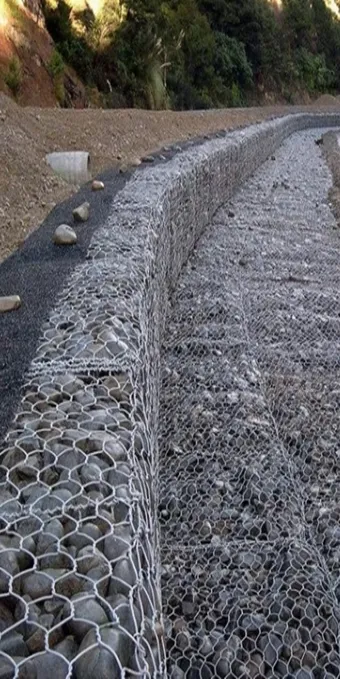
Earth-filled cellular barriers are collapsible wire-mesh assemblies that retain granular fill in connected cells, commonly using a fabric lining. Their practical advantages include compact transport before filling and the ability to form a continuous line of contained material. The completed installation nevertheless depends on its geometry, connectors, fill, foundation and site conditions.
A generic cellular unit must not be described as a military-certified or ballistic-rated product solely because a similar form has been used for protective works. Dimensions, a model label or the presence of earth fill do not establish blast, projectile or vehicle-impact performance. Any protective requirement must be specified and assessed for the actual installed assembly.
     wire-mesh cellular assembly
     +------------+------------+------------+
     | liner and  | liner and  | liner and  |
     | approved   | approved   | approved   |
     | fill       | fill       | fill       |
     +------------+------------+------------+
         compatible connectors / prepared base
2. Engineering mechanisms and load paths
The wire cage provides confinement, the liner retains material that could otherwise escape through the apertures, and the fill provides most of the completed unit’s mass. Connections between cells and between units help maintain the intended geometry. The functions are related but distinct: a strong cage does not make an unsuitable liner retain fines, and a durable liner does not establish wall stability.
Granular fill can rearrange under loading, settle with time and be affected by moisture. These behaviors influence the shape and contact conditions of the installed barrier. The selection of fill should therefore consider compatibility with the liner, drainage, placement equipment and the application rather than assuming that any available rubble is acceptable.
Performance in a protective application is assembly-specific. A report should identify the tested arrangement, materials, fill preparation, support conditions and outcome. It cannot be replaced by an unreferenced penetration-depth table, a generic explosive threshold or a statement that secondary fragments are impossible.
3. Design inputs and performance evidence
Start with the intended function and the site layout. Identify changes in level, corners, openings, access routes and any adjacent structures. Consider foundation bearing, sliding, overturning, drainage and maintenance as appropriate to the installation.
| Requirement | Information to define | Evidence or check |
|---|---|---|
| Cell and unit geometry | Overall dimensions, internal partitions and tolerances | Drawings and dimensional inspection |
| Mesh and connectors | Wire, welds, hinges, pins and coating | Agreed material and connection requirements |
| Liner and fill | Retention, puncture, durability and compatible fill grading | Liner data and trial placement where necessary |
| Foundation and layout | Ground support, level changes and terminations | Site assessment and approved layout |
| Any protective rating | The exact assembly and intended performance | Relevant complete test evidence and competent review |
Do not infer a protective rating from a material certificate. Equally, dimensional similarity to a commercial model does not establish interchangeability with its connectors or its assessed performance.
4. Material specification and acceptance
A purchase specification should identify the actual mesh opening, wire diameter, weld requirements and coating. State how dimensional tolerances and material properties are to be checked. Avoid presenting salt-spray exposure hours or coating mass as an unsupported service-life guarantee.
The liner should be specified by its function and applicable test properties, including retention, strength, puncture resistance and durability in the intended exposure. Its mass per area is useful identification but is not a complete performance specification. Explain any environmental or storage limitations that matter before installation.
Connecting pins, hinges and end details should be compatible with the supplied units. Inspect whether the connection can be assembled without damaging the lining and whether its engagement is visible after placement. If coated components are cut or damaged, use the agreed repair or replacement procedure.
5. Installation and inspection sequence
Step 1: Prepare the layout and base
Check the approved line, corners, terminations and ground condition. Remove unsuitable material and provide any required drainage or bearing preparation before unfolding units.
Step 2: Unfold under controlled conditions
Use the supplier’s handling method and protect the lining from sharp ground, machinery and snagging. Confirm that partitions and end panels are correctly positioned.
Step 3: Join and inspect the cells
Install the specified connecting pins and hinges. Check continuous engagement and inspect the fabric at joints before it becomes hidden by fill.
Step 4: Place compatible fill
Distribute fill progressively across adjacent cells using controlled equipment movements. Limit uneven loading and inspect the unit for distortion or liner damage during placement.
Step 5: Complete the acceptance record
Check alignment, fill level, connections and any specified top closure. Record the actual materials and installation conditions, and provide a maintenance and access plan.
6. Engineering FAQ
Q1: Does a cellular barrier automatically have a protective rating?
No. A rating must be supported for the actual assembly and the stated performance requirement. A generic product name or a material standard is not that evidence.
Q2: Can any available soil or rubble be used as fill?
The fill must be compatible with the liner, installation method and application. Unsuitable particles, organic material or moisture conditions can impair placement and retention.
Q3: Why are liner properties important?
The lining retains fill within a relatively open wire cage and must tolerate handling, placement and exposure. Mass per area alone does not establish puncture resistance, durability or retention.
7. Procurement checklist
| Include with the enquiry | Information to confirm |
|---|---|
| Intended use | Civil perimeter or another stated application, site layout and approval basis |
| Cell arrangement | Unit dimensions, panel wire, joints, corners and closures |
| Liner and fill | Retention, installation exposure, fill grading and placement responsibility |
| Performance evidence | Actual assembly identification and any independently required test scope |
| Delivery | Packing, handling method, unit labels and replacement components |
Provide the layout, fill specification and required evidence. A product name containing “explosion-proof” does not establish a blast rating.
Product pages describe the enquiry range. Any protective rating requires evidence for the actual assembly and agreed application.
Send the drawings and procurement requirements
8. References and scope
- WBDG — UFS 4-023-07, Design to Resist Direct Fire Weapons Effects. Facility-protection design context only; not a ballistic or blast test report for this product.
The linked Zhongman product pages describe the published supply range, not independent test evidence. State the required standard edition and acceptance documents in the order; compliance must be verified for the supplied product and batch.